To get started with CNC milling, begin by setting up your milling environment and selecting the right machine. Choose appropriate materials and tools, design your first project, program the machine using CAD/CAM software, and start running your milling operations.
Setting Up Your CNC Milling Environment
Choosing the Location
When it comes to a CNC milling machine, the location where this is placed is vital if you want your work and employees be safe. A suitable machine would run cool and need to be located in a stable vibration-free well-ventilated space for these reasons. For larger industrial CNC machines, as much space might be needed for compressors and coolant systems can add to that. Check that the floor can tolerate the weight of your sewing machine – roughly 2,000 to 8,000 pounds depending on its size and model.
Electrical Setup Installation
The CNC machines need a powerful consistent source power to work correctly The majority of CNC milling machines require a 208 to 240 volt supply and many also can use up to-classified as in general over-400 volts. Installation should be performed by qualified and licensed electrician to suit your specific electrical needs, this ensures that all work is compliant with the local Electrical Code.
Environmental Control
A well-regulated atmosphere is crucial in expanding the lifespan of the machine and guaranteeing exact operations. CNC EnvironmentThe Ideal temperature for an CNC environment should be between 68-72 degrees Fahrenheit with humidity kept under 75%. Control the temperature and humidity with air conditioning or even industrial cooling fans, plus prevent dusting through proper filters as this may affect your measurement accuracy.
Safety Measures
One of the most important considerations in a CNC milling setting is safety. Train all operators in the safety of electrical machines and emergency procedures. Install protective guards and emergency stop switches on all sides of the machinery. Store fire-extinguishers in accessible places and watch for cluttered aisles. Frequent safety drills and revising standard procedures decrease the potential for accidents.
Choosing the Right CNC Milling Machine
Machine Size And Power
There are several important factors to consider in order to find the appropriate CNC milling machine for your needs and one of them is sizes of parts you need. For a precision of just 0.0001 inches you will need – surprise, suprise! – one having a correspondingly smaller capacity machine suitable for small fiddly parts. Models that provide a larger working envelope and more power for bigger parts are worth to be taken into account. Standard models have a 40-inch-by-20 inch work area, although larger ones are available.
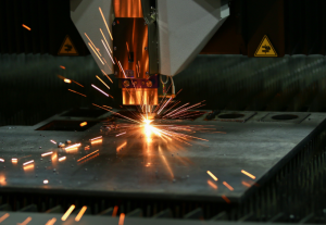
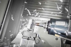
Machine Types and Applications
There are many types of CNC milling machines that have been developed for particular kinds of tasks. For plunge cuts and drilling, vertical mills (where the spindle operates in a vertically oriented plane) are often preferred, while horizontal mills make better heavy cutting loads. Advantageous for complex geometries and multi-sided machining, a 5-axis CNC mill can move the workpiece on five different axes at once.
Verification Of Rigidity And Machine Construction
The next determining factor of the quality of parts produced is how rigid a CNC milling machine functions. High quality cast iron or steel built machines ensure stable working environment and less vibration during milling. Make sure the weight of the piece you want to choose, showing that it is very well organized; high weight generally indicates more stability.
Speeds, Feeds
Spindle speed and feed rate are the most important which directly impact machining efficiency and surface finish. A machine that is able to adjust its pace when processing various types of compounds correctly is necessary. A spindle speed of at least 10,000 RPMs for metals and higher for softer materials. They should offer adjustable feed rates, some at up to 200 inches per minute for both fast roughing and precise finishing.
Integrated Linear Actuation Software
Regardless of whether the software is proprietary or third party, confirm that it will run on whatever CNC milling machine you intend to use. User-friendly control system that can accurately interpret your CAD designs. Siemens, Fanuc and Haas are common controllers that have good support for CAD/CAM software.
Materials and Tools for CNC Milling
Selecting the Right Materials
The type of material you select will be vital to the success of your CNC milling project. Popular materials are aluminum due to its machinability and high strength-to-weight ratio, stainless steel for good corrosion resistance and long life span; brass with smooth machining capabilities available, excellent electrical conductivity. You should be choosing a material based on specific properties such as tensile strength or hardness, thermal conductivity etc.; that is how you will know best what the end user purpose of your factored part;
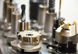
Understanding Tooling Options
When choosing the cutting tools used in CNC milling, we must consider rate of hardness material, machining speed and quality. Carbide tools are also widely used due to their longer life span and they can be run at higher speeds compared with high speed steel (HSS). Tooling options such as end mills, face mills and thread mills are examples of this type specific to the appropriate operations. Common types of mills used for milling include end mills (for cavity cutting), face mill cutters or body only tools, threadmills etc.
Tool Holders and Attachments
The tool holder is one of the factors that affect precision stability in CNC milling. HYDRAULIC & SHRINK FIT HOLDERS: Offers high clamping forces and reduced vibration to increase machining accuracy Most tool holders are available in CAT, BT or HSK type – though the spindle interface inside the machine will determine which to use for an effective balance and fit.
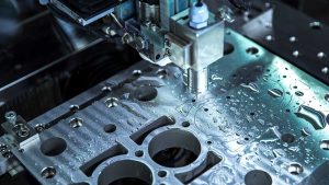
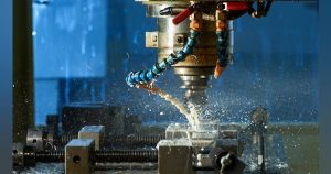
Coolants and Lubricants
Proper coolants and lubricants are required to avoid overheat as well as ensure proper machining. Water-soluble coolants function well as they provide excellent cooling properties and work with multiple types of materials. Because oils can be used with materials like aluminum, the fact that they reduce sticking and produces a smoother finish makes them more desirable. The choice of the liquids have to consider environmental impact and impacts on human health such that fluids which will not cause any harm during its application be chosen.
Feeds and Speeds Calculations
A proper computation of feeds and speeds is necessary to improve the cutting conditions, increase tool life as well as achieve required surface finishes. For the material and specific tool being used, spindle speed, feed rate, depth of cut, amount that the dadoes will overlap each other as well as even how many flutes are on a given endmill all need to be taken into account. These calculations can also be assisted by Software and Machining Calculators that provide recommendations specific to the tool material, size,,and workpiece material.
Designing Your First Project
Starting with CAD Software
When designing your first CNC project, you will want to start by picking Computer-Aided Design (CAD) software that works best with what skills and needs for the project. Software such as Autodesk Fusion 360, or SolidWorks present a more professional software option that suits users of beginner and advanced skill. You can design 3D models in these software where they directly translate into machine operations. Free software like SketchUp or TinkerCAD can even be enough for simple projects.
Creating the Design
Firstly, draw out your idea on paper or directly into copy of a drawing software like CAD For your first project, make simple designs only; take for instance basic geometric shapes such as rectangle or circle. Measurements must be exact and have a specified tolerance depending on the material you are using as well as another special aspect of the milling procedure that will apply. For example, if you are going to be machining soft wood then perhaps although of the potential for it warp slightly once its machined.
Tolerances and Material Allowance
The tolerances are what underpin the fit and function of CNC machined parts. ±0.005 inches (±0.127 mm) is adequate for the majority of beginner projects But if you’re dealing with metals, it might need to be more strict on tolerances. And keep in mind material allowances for finishing processes such as sanding or painting, which can sometimes change the dimensions of your final piece a little.
Design Export to Machining
After finalizing your design on CAD, the next step is to export it in a format compatible for Computer-Aided Manufacturing (CAM) software. STEP and IGES formats are very useful for an interchange between different software packages, as they offer a simple geometry solution. Your design file must contain complete details like dimensions, tolerances or special notes on any features requiring extra care during milling.
Mill Process Simulation
How to Choose CAM Software
Finding the right Computer-Aided Manufacturing (CAM) software is important, its what turns your CAD model and into G-Code, which makes all CNC machines operate. Such as Fusion 360 Mastercam SolidCAM, these are the well-known software for beginners with a neat and clean User interface through which they can easily follow Milling strategies. Most CNC in the market are equipped with simulation tools to preview how the machine will implement these operations.
Generating Toolpaths
This route the cutting tool will follow is defined by some set of parameters involving that path generated and this particular process called Toolpath generation. The CAM software presents a menu of available toolpaths based on the type of operation (pocketing, contouring, drilling) or specialized task at hand—such as engraving. The values of cutting depth, stepover and feed rate parameters should be set based on the material utilized and an actual cutter combination used. As an example, aluminum can be fed using a faster feedrate than stainless steel.
Setting Up the Cutting Tools
In this CAM software, we should set up that tools are going to use : size and material. Correct tool setup will mean that G-code generated watches the shape of your physical tools. The speed and quality of the cut change depending on diameter, length, number of flutes; therefore these details are used for software programming.
Simulating the Toolpath
It really is necessary to simulate this code in your CAM software before you send it off back down the wire (assuming your running a CNC machine). This ensures there are no possible crashes or the tool will dive too deep, move further than it should and mill air. The simulation helps avoid expensive mistakes and also save possible damage to the CNC machine.
Exporting and Loading G-code
After the simulation yields that everything is all set, then comes exporting the G-code from your CAM software. This code is then sent to the CNC machine, via USB (etc.), or direct input. Make sure the G-code knowledge works together with your CNC machines management as some machine manufacturers could differ in syntax
Running a Test Piece
If you are trying to cut a frame like this, if we suggest that before cutting the final piece is tested by running on a material that would be scrapped. This helps ensure that everything is working as expected, without ruining the end material or product. The information gained from the test can be used to tailor the cutting condition by adjusting feed rate and spindle speed as desired.
Running Milling Operations
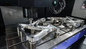
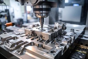
Initial Machine Setup
Make CNC Machine Setup Before Starting Milling Operation! It includes more than pretty knobs, such as inspection of: the commodities in their holders; that workpieces are sturdy against the machines table; and each-axis originated. Determine lengths of tool and input this information to the CNC control to program depth cuts accurately As well as to make sure that the coolant system is working, so it doesn’t overheat in operation.
Loading the G-code
Upload the G-code to CNC machine control panel. Our tool path saves g code file and you can see all programming instructions, incremental distances along with speed limits as feed rates. Review the Code to Avoid Errors which could get skipped during simulation phase. Most CNC operators like to run it in ‘air-cut’ mode first, where the machine runs the program without actually cutting (adding water) material so that they can see if all of their toolpaths are correct.
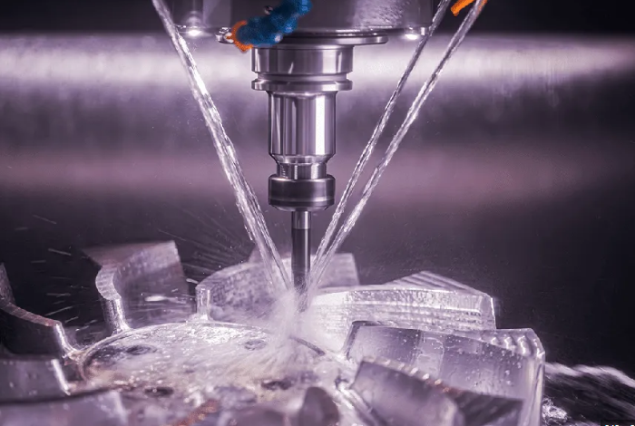
Watching the Milley Process
However, as the physical milling actually begins it is necessary to keep a careful watch on things — especially if this is going to be complex or take a long time. Look out for excessive vibrations or noises as they may indicate a dull tool or that you are cutting too aggressively. Attend to the rate of material removal, ensure that chips are evacuated with the coolant flow in order not be re-cut and which can affect surface finish as well tool life.
What Adapts Throughout the Operation
You may need to modify these settings slightly and optimize the milling process accordingly, depending on your observation. It might be adjusting spindle speeds, feed rates or it could even be changing the cutting tool completely if the current one is not doing its job effectively. By doing so, adjustments are carefully considered and not just trial & error based changes which help retain the form of part being machined.
Quality Checks
Conduct routine quality check during milling progress, especially after minor or major operations or instrument change. Measure with manufactory differentials, micrometers or other measuring devices (in case of CMM machines) to check dimension and angles according drawings. Record these dimensions in your quality control measures and use the data as part of troubleshooting any problems, as well for future records.
Post-Op Cleanup and Maintenance
When finished with the milling, clean out all chips, debris and coolant as these can hold any dirt that lands on them adjustable wading to rust. Examine with the unit to confirm If your Software holders or spindle are either worn out, broken. You have to carry out these maintenance inspections regularly if you want the machine to last longer and ensure it remains accurate and efficient for your next projects.