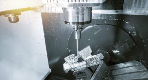
A CNC system comprises a controller, drive motors, feedback devices, machine tool, interface devices, and software.
Central Processing Unit
A central processing unit is the heart of a CNC system, as it executes the commands and processes data necessary for the machine to perform its functions. It performs a variety of functions and has numerous components. Below is some information about its key functions, responsible roles, and specific components.
Functions and Purposes
The main functions of a CPU are as follow:
-
Interpreting G-code commands: these commands are received by the sensors of the CNC machine and indicate the movements it must make
-
Coordinating the work of axes: the CPU sends signals to the different axes of the machine to ensure they move simultaneously, which is necessary for precise machine operation
-
Monitoring the work of the machine in real time: the CPU constantly controls the status of different components of the machine and adjusts its work when needed for optimal functioning
Core Components
-
Microprocessor: serves as the core of the CPU by performing all the necessary calculations and executing instructions. Modern CNC systems often use multi-core processors to manage the numerous tasks that need to be performed
-
Memory: stores the G-code programs, as well as paths the tools must take and the parameters of the machine. Typically, the CPU uses random access memory to provide short-time access to this information and non-volatile memory to store low-level machine data.
-
Input/output interface: the I/O interface of the CPU manages the means of communication between the CPU and the rest of the machine, including all its sensors, instrument actuators, and machines.
For instance, the Fanuc 30i-B series is often used in industrial applications and has a powerful and efficient CPU. It can process up to 256 axes on the CNC machine, performing real-time measurements and adjustments. The CPU has a fast microprocessor and employs efficient memory allocation to ensure the CNC’s precise work is executed. As it can be seen, a CPU is an essential part of the CNC system, and modern CPUs help ensure that a CNC works accurately and quickly.
Input Device
Every CNC system requires an input device for the purpose of inputting data, commands, and instructions. The overall purpose of input devices is therefore to enable operators to interact with the CNC system. Here are the details on how that works:
Types of Devices Used
Various input devices can be used with CNC systems, and no definite limit exists with regard to the variety of such tools:
Keyboards: The primary type of input devices used for entering G-code commands, inputting data manually, and editing programs. Keyboards are often rugged and adapted for use in an industrial environment, using industry-specific layouts and markings.
Mouse and Touchscreen: An important interface tool that helps navigate through CNC software, select options, and modify parameters. Touchscreens are growing more popular due to the intuitive nature of the devices.
Remote Handwheel: Also known as an electronic handwheel or jog pendant, the tool permits operators to adjust and control machine axes manually. The remote handwheel is especially useful for setup and troubleshooting.
Functions Performed and Features Used
Input devices employed with CNC systems are used to perform the following functions:
Program Entry: Input devices often possess functionality that allows operators to input and modify the relevant programs.
Parameter Setting: The tools help configure a wide range of machine parameters, such as feed rates, spindle speeds, and tool offsets.
Manual Control: This function enables the manual control of machine axes for the purpose of setup, inspection, and testing the part.
Example Used
One possible example is the operator panel installed in the Siemens Sinumerik 840D CNC system. It combines three different input devices, two of which were already described: the device features a full keyboard with various keys and even a touchpad, a large touchscreen used for the navigation through multiple severe-related menus, and a handwheel. This arrangement enables operators to use the most efficient and convenient tools to work with the machine, with touchscreen capabilities allowing movement through the more comprehensive and precise options. The handwheel is used when manual machine control is necessary to solve problems or for the purpose of initial setup of the machine.
Integration Used
Every input device in a CNC system must be integrated with the device, and modern CNC systems contain input devices integrated via cable connections to the CNC CPU
Ergonomics
Given the intense, prolonged nature of the work with CNC devices, ergonomics is of paramount importance. A suitable input device should enable work for a prolonged period without a need for repositioning or breaks. Details such as touchscreen angle adjustment, combined with the necessary function keys on the periphery of the devices, can help in this respect.
Machine Control Panel
A machine control panel is an essential interface of a CNC system, serving as the means of communication and command between the machine and the operator. Below are the detailed explanations of its functions, components, and a nominated real-world example.
Functions and Duties
A control panel enables an operator to:
-
Commence and Stop Machining: jump, stop, or pause any operation according to the requirements.
-
Monitor the Status: program-related in-time information such as spindle speed, feed rate, or tool location.
-
Mechanize the Input and Adjustment of Data: manually put down the command or modify the current settings.
Components
Usually, an advanced CNC machine control panel consists of the following parts:
-
Monitor: provides the visual feedback and enables the operator to monitor the process. Like the majority of modern electronic devices, the most recent panels are equipped with high-resolution touch displays.
-
Control Buttons and Switches: the panel contains sections of buttons and switches for separation of different commands. In most cases, they are color-coded or marked with icons for better structure.
-
Handwheel and Joystick: used for manual control and movement of machine axes; can be particularly useful during the installation and inspection.
-
Indicator Lights: signify the current progress and status, i.e., whether the machine is running or the tool is being deployed.
Real-World Example
The machine control panel that I have chosen for this purpose is Mazak SmoothX CNC. It is equipped with the 19-inch touchscreen display for greater information. As demonstrated in many studies, a better interface is more likely to be user-friendly, thus easier to use. Another advantage of the SmoothX panel is the feature of gestures and customizable layout. Along with that, the buttons are located in a way to reduce the unnecessary movement of the operator and simplify any operations, decreasing the setup timing by thirty percent.
Integration and Connectivity
Interaction with the other units of the CNC system and the transfer of the data is organized by an integral part of the control panel, i.e., the Central Processing Unit. Modern panels offer higher up-to-date connectivity options, such as Ethernet or USB, which allow conducting the data management more effectively.
Safety
Taking into consideration the massive workload of CNC machines, a high level of security should be guaranteed. For this reason, the modern machine control panel is equipped with such options as:
-
an emergency stop button,
-
a protective cover of the controls, and
-
error alarms.
Ergonomics
The comfort of the operator is another aspect to consider. Many sets allow adjusting the height and angle of the screen for a more efficient view. An example of this is Okuma OSP-P300A, as it contains the extendable arm and the well-structured layout of controls in order not to make the timing less efficient with unnecessary movements.
Programmable Logic Controller
The programmable logic controller is one of the central elements of a CNC system and is responsible for the management and automation of the equipment. This paper will briefly discuss its functions and responsibilities, the main components, and a real-world example of a PLC in the CNC systems. The final part will provide information about the way a PLC is integrated into a CNC system and then briefly review its program and potential customization and the main features that facilitate them.
PLC Functions and Responsibilities
A PLC was originally designed to automate a wide range of manufacturing processes that require constant or periodic control. The functions of a PLC within a CNC system include the following:
-
process automation, i.e. the automation of repetitive tasks, such as tool change or material replacement, or loading;
-
real-time control, i.e. the implementation of machines control and monitoring in real time;
-
the connection with other elements allowing the machine to both control the system’s elements and receive their essential data.
PLC Components
The main components of this element are the following:
-
the central processor unit that processes the data from the sensors and other devices;
-
the input/output devices, plunge sensors, and motors;
-
power supply;
-
communication ports, connecting the PLC to HMIs and SCADA systems.
Real-World PLC
A Siemens S7-1500 is a frequently applied PLC for any kind of CNC. It has a high Speed of Processing of up to 1,000, 000 operations per minute, integrated safety features, and a Hot-Swap functionality.
To manage the production of the engine at the automotive plant of my choice, it would be possible to integrate the PLCs in a way that the CNC machines monitor the process of the manufacturing of the plastic details and steel parts of the cars. This integration will include information exchange:
-
on the status between CLC plants and the CMC CPU programs;
-
between the CLC and the CNC regarding the working parameters of the machine tool;
-
the exchange of signals on the start and end of the operation.
the execution of the program including the monitoring of pressure of the oil that may influence the cotserv processing. To achieve this, the operators can configure the central processor unit in the specific order in one of the following languages:
-
Ladder Logic;
-
Function Block Diagram;
-
Structured Text.
Servo Control Unit
The servo control unit is one of the significant parts of CNC systems, which is responsible for controlling the motion of the machine with high precision. In the present post, its functions, components, and real-world examples will be discussed in detail.
Functions and Responsibilities
The unit performs several highly important functions:
Motion Control: Keeping speed, position, and torque of servo motors in check, it ensures correct motion and prevents deviations.
Feedback Processing: Receiving and processing feedback from the encoders and other types of sensors, the unit ensures that the control is correct.
Coordination with CPU: The unit and the central processing unit should work together to perform complex motion sequences.
Key Components
The unit’s structure includes the following constituents:
Servo Drive: The part is responsible for transforming the received control signals into electrical currents, which finally result in the motor being driven as the position, speed, and torque are commanded.
Feedback Device: Usually encoders and resolvers are used to provide real-time data on motor position and speed, which is vital for controlling it. The coordinates are sent to the control unit through the feedback devices.
Control Algorithms: The unit contains future motion planning algorithms and current control algorithms that should maximize motor performance, minimize errors, and enhance speeds.
Real-World Example
One of the most common examples is the Yaskawa Sigma -7 servo control system, an essential part of the majority of CNC systems. The system:
Is Precise: It is able to reach up to 20-bit encoder feedback, ensuring high measuring accuracy.
Is Fast: Reaching up to 3.1 kHz of frequency response, the system can ensure that no motion deviations occur and the precision is very high.
Is Robust: The system is capable of working at high speeds and under load and processing the hardest motion sequences.
Real-world Application
The given control system is applied in the aerospace industry that machines highly-precise and small details for the majority of its machinery, such as ‘vanes, blades, and blisks’. There is a great contribution of the given system to this industry as aerospace applications often need too high accuracy and response speed for the ordinary controllers. Integration
Finally, integration of the control involves:
Communication Protocols: The unit communicates with the CNC’s CPU using one of the available protocols, which can be EtherCAT, CANopen, or Mechatrolink, all of which are developed for real-time communicating of data. The synchronization of multiple axes is required when the motion is highly complex. The operators can use the servo control unit to change settings relating to specific parameters, such as acceleration, deceleration, or jerk.
Feedback Loop
The existence of a reliable feedback loop is critical for the servo control unit’s functioning:
-
The feedback device constantly communicates to the servo control unit the actual position of the motor or whatever structure the unit is trying to control.
-
The unit constantly compares this information with the position it has been commanded to go to.
-
In case of any discrepancy, the control unit starts adjusting the unit’s movement to minimize this error.
Safety and Reliability
Servo control units are designed with specific safety features integrated:
-
The system often includes measures to prevent an overload, which can destroy the motor and the drive, such as a short circuit.
-
To guard against overheating, the design of the unit and motor provides thermal means and even fan cooling in some cases.
-
In many modern units, it is possible to check the system’s state through a set of diagnostic tools, which can also predict how long before a failure will occur.
Real-World Application and Benefits
The example of a modern servo system might be the Fanuc Alpha i Servo System used in CNC machines of many kinds in the industrial, automotive, construction, and many other industries. The benefits of using this system include:
-
Reduced energy waste by using regenerative braking to power the unit.
-
A much smaller design compared to older models can save an engineer a lot of space and even change the ways the machine can be designed.
-
The units have very high performance, accurately controlling the speed of the motor, which can be very high during the cutting process, making it not only very precise but also very rapid.
Display Unit
The display unit plays a crucial role in the operation of a CNC system, providing the operator with real-time visual feedback and control over the machining process. Let us discuss its functions and responsibilities, key components, and application with the help of a real-world example in further detail.
Functions and Responsibilities
The display unit performs several crucial functions:
-
The display unit provides real-time visual feedback and allows the operator to monitor and control the machining process. For example, it can display data about the machine status, position of the tool, or the current speed and pressure of the cooling liquid.
-
The display can also serve as a unit for data input and control. The operator can use it to input a new command, choose a different program to follow, or adjust the parameters .
It also should display messages about diagnosed errors and expected failures .
Key Components
A typical display unit will have several components:
-
Screen. The screen unit is the main part of the display, usually taking the form of an LCD, LED panel, touchscreen, or a combination of the three . Modern CNC devices widely choose touchscreens instead of other options, as they are capable of better resolution and interactivity.
-
Control panel consisting of buttons, switches, and knobs for manual control and quick access to important commands.
The user interface software should be easy to use and learn. It combines to form a graphical user interface that is used to communicate with the machine.
Real-World Example
Siemens Sinumerik Operate 15.6-inch touchscreen is a modern example of a CNC display unit . Features of the device are the following:
-
The display has a resolution of 1366 x 768 pixels to provide clear visual feedback.
-
The display is capable of detecting up to ten simultaneous touches to enable multiple touch commands such as zooming, panning, or rotating the view.
-
The screen’s content can be customized, with the operator deciding which information will be displayed on the main screen. For example, one can use it to monitor the level of the coolant or its pressure and speed.
Integration with CNC Systems
The display unit seamlessly integrates with other CNC system components:
-
Data Connectivity: Connected to the central processing unit and programmable logic controller via data buses. The data is transferred in real-time to keep the display synchronised with the processes carried out.
-
Software Updates: Allows updating of the display system via over-the-air updates, receiving software improvements and added features through an internet connection.
-
Remote Monitoring: Advanced displays also enable remote monitoring and control of the CNC system.
Importance of Display Quality
Moreover, the display itself plays a crucial role in determining the efficiency and performance of the CNC system:
-
Clarity and Brightness: Makes small items visible easily, powerful displays eliminate the need to magnify the screen and reduce eye strain. Furthermore, bright displays often reduce inaccuracies caused by having to identify item details in a darker environment.
-
Touch Sensitivity: A highly reactive panel increases the speed at which operators can use the system, ultimately minimizing downtime. Increased touch sensitivity often results in a more user-friendly experience.
- Durability: Capable of withstanding heavy use and industrial conditions. The screens are resistant to dust, liquid, and can also withstand mechanical vibrations.
Real-World Application and Benefits
One of the examples of CNC systems is the Mazak SmoothX control system. The control system utilises a display unit which includes:
- 19-Inch Multi-Touch Display: It is a sizeable and straightforward interface for visualisation of more complex machining tasks.Interactive 3D Simulation: The
- system can simulate tool paths and orientation and even creates a virtual tool or block of material in 3D. Consequently, the setup time of tools is reduced by eliminating any unnecessary paths, and the risk of crashes is minimised.
-
User-Friendly Interface: This controls system allows for simple guidance during setting with paper drawings. It is also suitable for less experienced operators.
-
Within a precision engineering firm and specifically in the cicumstances of mold making, using the Mazak SmoothX display unit can be implemented to more efficiently mange the machining of tools. In this case, the interactive 3D simulation can be effectively utilised by the machine operators to set up tool paths for more complex pieces. The systematic 3D visualization can enable operators to simulate tool paths and more closely monitor the production process to avoid errors and minimise part failures in such a delicate process as mold making.